
How to Verify Grounding Continuity of a PCB-Integrated Shielding Can Before Mass Production — A Technical Diagnostic Gui
Why Grounding Continuity Matters — Especially on First Use
For electronics solution providers launching new communication modules, IoT terminals, or smartphone reference designs, the PCB-integrated shielding can is often the first high-frequency structural component where grounding continuity directly impacts EMI pass/fail outcomes. Unlike generic enclosures, these cans rely on metal-to-PCB contact at multiple flange points — not soldered joints — to form a low-impedance return path. A single ungrounded corner can degrade shielding effectiveness significantly above 1 GHz.
Yet many teams treat grounding as a ‘post-stamping’ verification — only to discover intermittent failures during pre-compliance testing. This article diagnoses why that happens — and what you can verify before mass production begins.
Myth vs. Fact: Common Misconceptions About Shielding Can Grounding
| Myth | Fact |
|---|---|
| “Any conductive surface contact guarantees grounding.” | Grounding requires continuous metal-to-metal contact under assembly force. Surface finish (e.g., tin plating vs. chemical nickel), flange flatness, and PCB pad coplanarity all affect contact resistance. |
| “Thicker material always improves grounding.” | Excessive thickness reduces flange flexibility, increasing risk of incomplete seating or localized lifting — especially on fine-pitch modules. Zhuoyi’s thickness selection is calibrated per frequency band and rigidity requirement, using SPCC, SUS304, or AL1060 base materials. |
| “Coating coverage doesn’t impact grounding if the base metal is conductive.” | Partial insulating coatings are intentional — but must avoid flange contact zones. Coating overlap on flange surfaces can break continuity, regardless of base metal conductivity. |
What You Can and Cannot Validate Pre-Mass Production
Verifiable before tooling release:
- Flange geometry and contact area dimensions (from final mold design drawings)
- Base material selection (SPCC, SUS304, or AL1060 — each with distinct conductivity and spring-back behavior)
- Surface finish specification (e.g., tin plating for SMT compatibility; chemical nickel for corrosion resistance and stable contact resistance)
- Dual-positioning features (guide slots + flange/groove system) — confirmed via GD&T annotation on engineering drawings
Not verifiable until first physical sample:
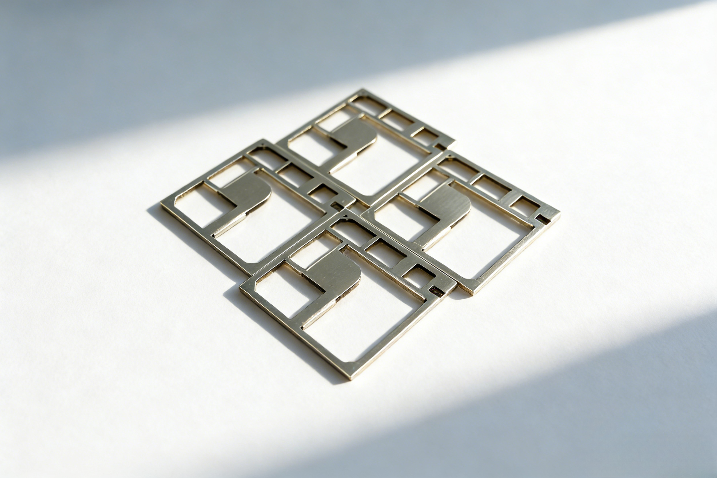
- Actual contact resistance across all flange points under real PCB warpage and reflow conditions
- Long-term bounce-life of spring-loaded flanges after thermal cycling (requires accelerated life testing)
- Final grounding stability after board-level drop or vibration — depends on full system integration
How Zhuoyi’s Integrated Mold Development Supports Grounding Validation
Dongguan Zhuoyi Precision delivers more than stamped parts — it delivers grounding-intent manufacturing. For your first-use shielding can:
- Mold design includes grounding-critical GD&T: Flange parallelism, edge radius control, and slot depth tolerances are built into the mold — not added post-stamp.
- Material selection is application-aligned: SPCC offers optimal cost/performance balance for most communication modules; SUS304 provides higher corrosion resistance for outdoor IoT terminals; AL1060 enables lightweight, high-conductivity solutions for compact tablet modules.
- Process-controlled surface finishes: Tin plating ensures reliable solder-wettability and low initial contact resistance; chemical nickel maintains stable resistance over time — both applied under controlled production conditions.
All this is delivered within Zhuoyi’s end-to-end capability: from mold R&D and precision stamping to quality inspection and packaging — specifically for electronics solution providers including communication module companies, IoT module companies, and POS terminal manufacturers.
Next Steps for Technical Evaluation
If you’re evaluating your first PCB-integrated shielding can:
- Request Zhuoyi’s grounding-focused DFM checklist — covering flange width, minimum bend radius, and coating exclusion zones.
- Share your module’s PCB stack-up and flange footprint — we’ll cross-check against our standard clip compatibility and recommend base material and functional thickness range.
- Ask for a grounding continuity test report template — aligned with industry-standard contact resistance measurement practices and acceptance criteria for Class 2 electronic assemblies.
Grounding isn’t assumed — it’s engineered, verified, and repeated. Your first shielding can should be grounded in data — not hope.
Recommended
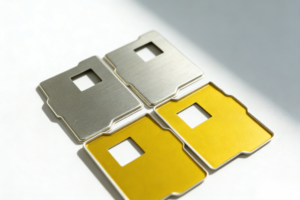
EMI Shielding Can
Precision EMI shielding cans designed for high-frequency circuits in communication modul...
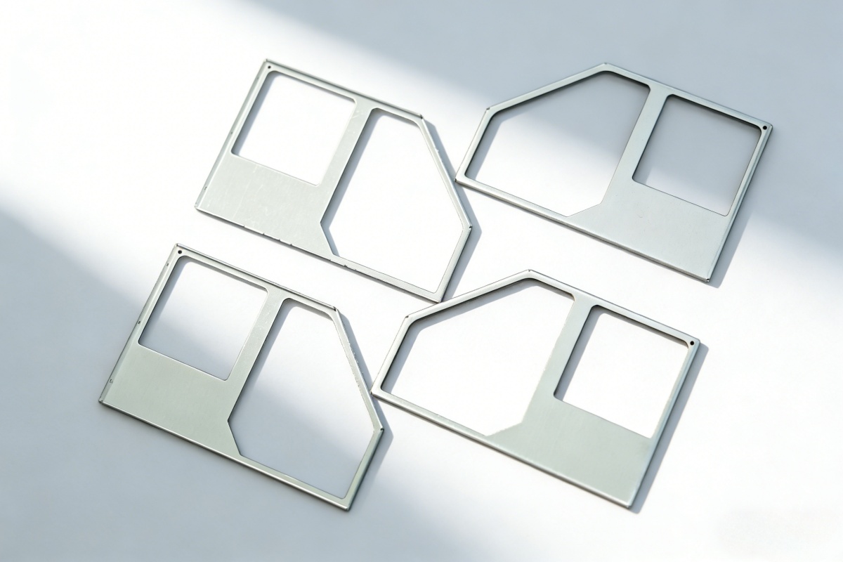
Shielding Can
An integrated metal enclosure structure designed for rapid installation and reliable EMI...
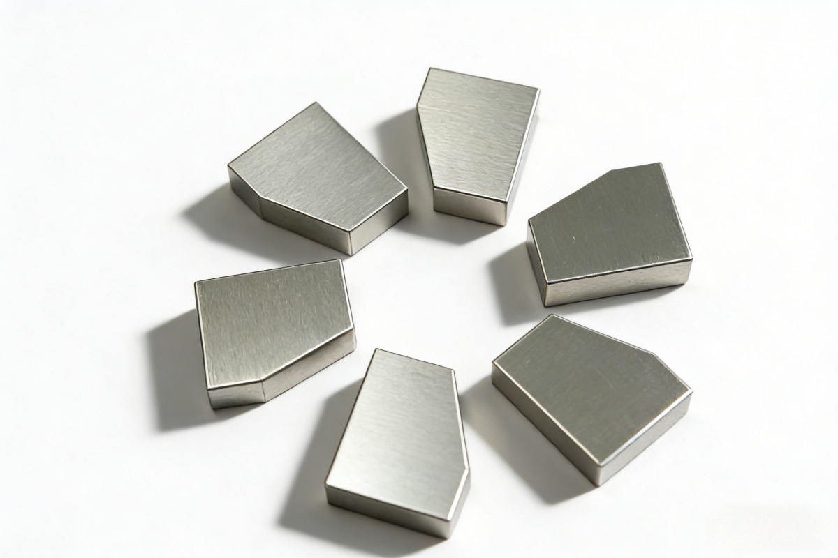
EMI Shielding Cans and Covers (EMI Shielding Structural Components)
Precision EMI shielding cans and covers engineered for high-frequency electronic devices...