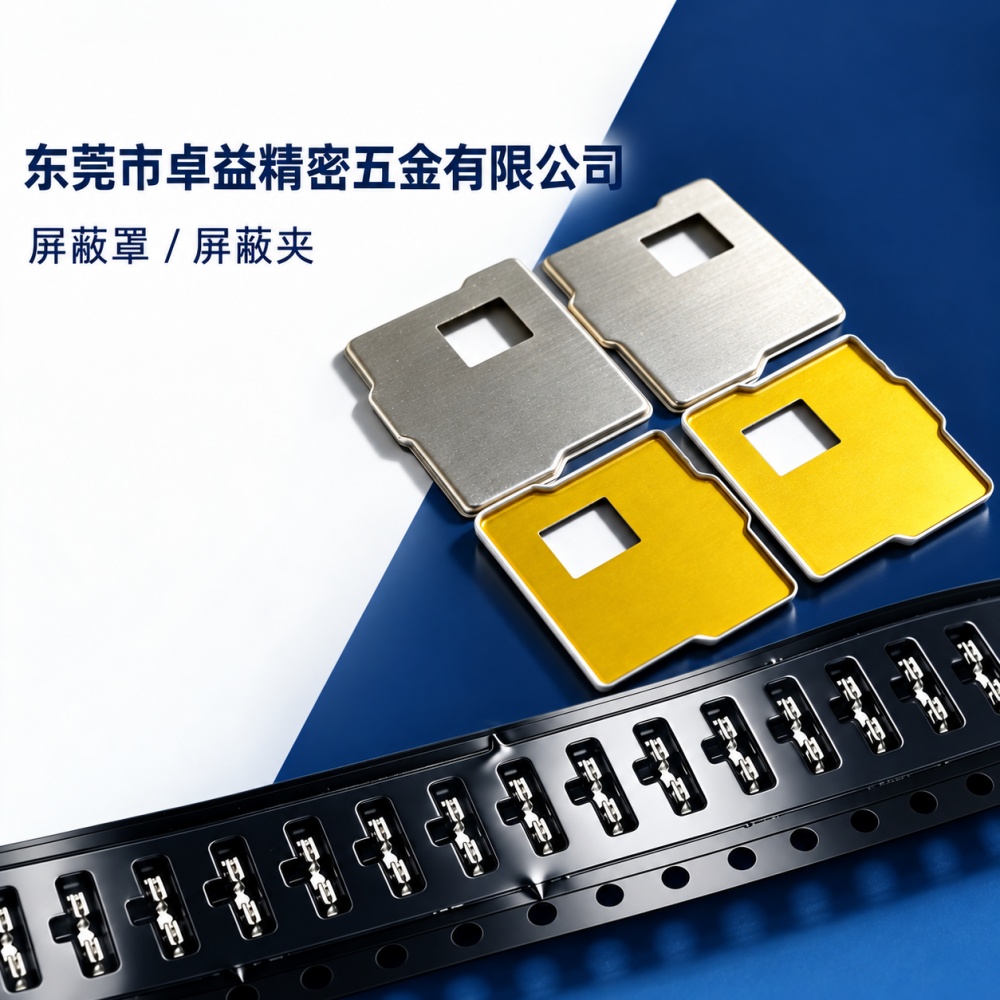
EMI Shielding Cans and Covers (EMI Shielding Structural Components)
Precision EMI shielding cans and covers engineered for high-frequency electronic devices such as communication modules and IoT modules. Available in one-piece, two-piece, and partial insulating coating configurations to meet EMI/RFI isolation, mechanical fixation, and mass-assembly reliability requirements.
Highlights
- Bidirectional EMI/RFI shielding for high-frequency applications including communication modules and IoT modules
- Customization options: one-piece, two-piece, and partial insulating coating configurations
- Integrated mold development and precision stamping service with dimensional tolerance control of ±0.05 mm
- Rapid prototyping: 7 working days for small-batch samples, including 3D scan comparison report
- 100% inspection covering CMM dimensional measurement, 48-hour salt spray testing, and grounding impedance ≤10 mΩ
Specifications
- Typical Materials
- SPCC (cold-rolled carbon steel), AL6061-T6 (aluminum alloy), SUS304 (stainless steel)
- Surface Finishes
- Chemical nickel, electroplated nickel, zinc-nickel alloy, conductive oxidation (for aluminum), partial insulating coating
- Thickness Range
- 0.15–0.8 mm (selected based on structural strength and springback requirements)
- Minimum Internal Bend Radius
- 0.3 mm (SPCC) / 0.5 mm (AL6061)
- Standard Tolerance
- Overall dimensions ±0.05 mm; flatness ≤0.08 mm
EMI Shielding Cans and Covers (EMI Shielding Structural Components) are critical EMI shielding structural components in electronic modules, widely applied in communication modules, IoT modules, smartphone/tablet solutions, POS terminals, and industrial control equipment. Their core function extends beyond simple coverage: by forming a metallic enclosed structure, they generate a Faraday cage effect to achieve bidirectional electromagnetic isolation under high-frequency operating conditions.
I. Core Functions of EMI Shielding Cans and Covers
- Radiation Suppression: Constrains electromagnetic energy leakage from high-power units on the PCB—such as RF chips and power amplifiers—to reduce interference with surrounding circuits or wireless devices;
- External Interference Blocking: Shields sensitive receiver circuits (e.g., LNAs, VCOs) from external electromagnetic fields generated by power supply noise, motor start/stop events, or coexistence environments (e.g., Wi-Fi/Bluetooth), thereby improving signal-to-noise ratio and communication stability.
II. Key Boundary Conditions for Selection
Shielding performance is highly dependent on structural compatibility; non-standardized application often leads to degraded performance. Through servicing hundreds of module projects, Zhuoyi Precision has identified the following critical technical boundaries:
- Ground Clearance: The gap between the bottom of the EMI shielding can/cover and the PCB pads/components should be ≥0.3 mm; insufficient clearance may cause parasitic coupling or assembly interference;
- Apertures and Gaps: Ventilation hole diameter should be ≤λ/20 (e.g., ≤3.5 mm for 433 MHz); slot length must be
- Grounding Continuity: Low-impedance grounding loops must be established along all four sides via multiple spring-finger contacts or conductive adhesive; single-point contact significantly degrades low-frequency shielding effectiveness;
- Material and Surface Finish: Commonly used materials include SPCC with Ni plating (balancing conductivity and corrosion resistance); for high-frequency applications, AL6061-T6 with chemical nickel or stainless steel 304 are options; insulating paint is applied only locally to prevent short circuits and must not cover the entire grounding surface.
III. Zhuoyi Precision’s Process Assurance Capabilities
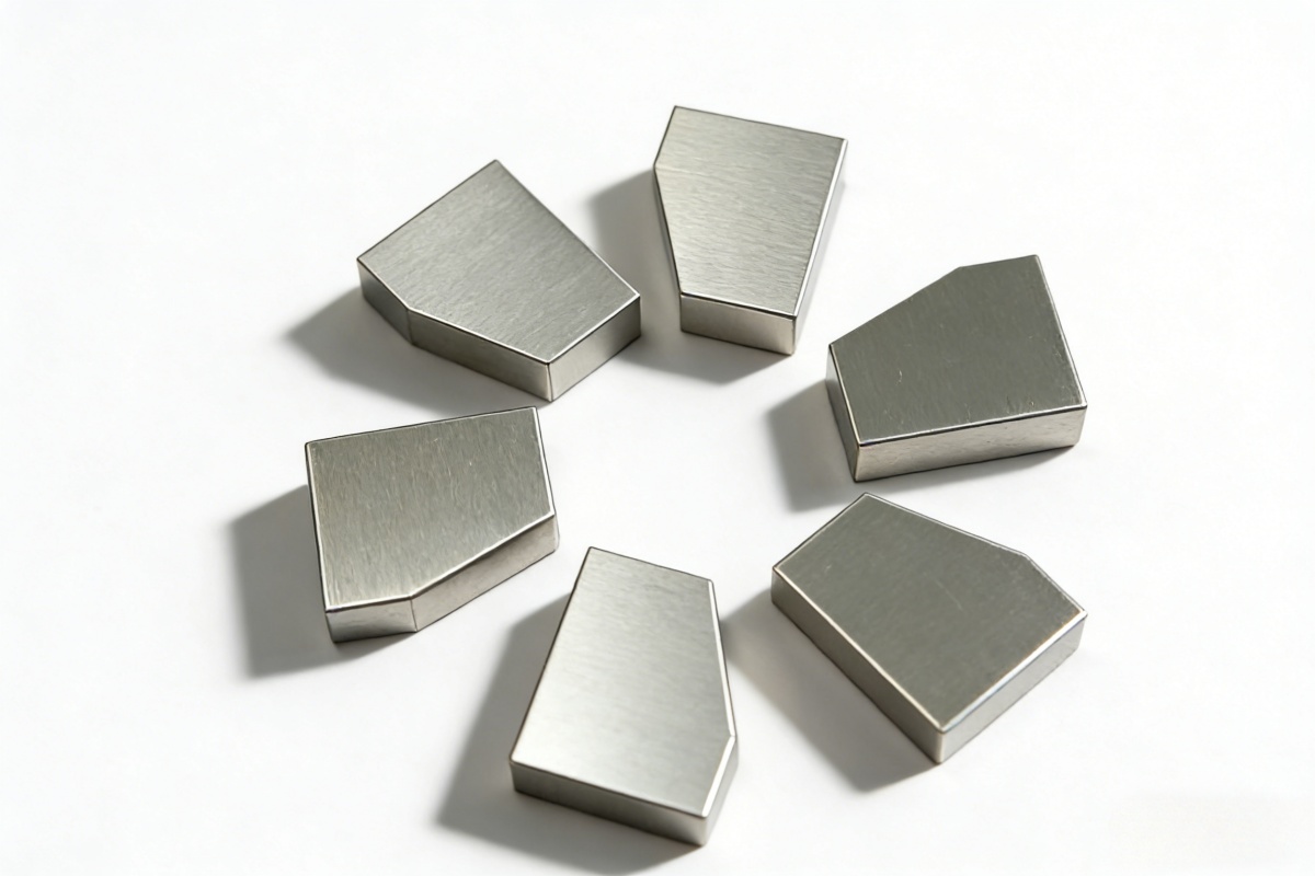
Unlike general metalworking shops, we have built an end-to-end capability—from structural validation to mass production delivery—specifically for electronics solution customers:
- Die-Level Precision Control: Stamping tolerance ±0.05 mm; flatness ≤0.08 mm—ensuring precise fit with module housings and PCB locating pins;
- Rapid Small-Batch Response: Supports prototyping runs of 1–500 pieces; first samples delivered within 7 working days, including 3D scanning comparison reports;
- Mass Production Consistency Assurance: Full-dimension automated inspection (CMM + optical projection), salt spray testing (48 h), and spot-checking of grounding impedance (≤10 mΩ);
- Collaborative Development Support: Supports customers’ hardware engineers in shielding effectiveness simulation (CST/ANSYS), structural stress analysis, and DFM optimization.