
Why Your First PCB-Integrated Shielding Can Isn’t Passing EMI Compliance — A Diagnostic Guide for Compliance Managers
The Problem Is Not the Shielding Can — It’s the Adoption Gap
You’ve selected a PCB-integrated EMI shielding can for your new 5G communication module or compact IoT terminal. The design passed simulation. The layout includes guide slots and flange/groove features. Yet during pre-compliance testing, radiated emissions exceed limits above 1 GHz—and rework cycles are mounting.
This is not uncommon. But it’s rarely due to inherent shielding performance. More often, it stems from misalignment between specification intent and real-world implementation boundaries—especially during first-time adoption by compliance, hardware, or procurement teams unfamiliar with precision stamped structural components.
Below is a diagnostic framework built exclusively on verified facts from Dongguan Zhuoyi Precision’s documented capabilities—not industry generalizations.
Fact-Based Diagnostic Checklist (Based on Verified Product Data)
1. Myth: "Any metal enclosure qualifies as an EMI shielding can."
Fact: Only integrated can-and-lid structures with dual-positioning systems (guide slots + flange/groove) ensure repeatable assembly accuracy—critical for maintaining shielding integrity across the GHz range.
→ Source: Product ID 718, 'Shielding Can | PCB-Integrated EMI Shielding Structure'
2. Myth: "Material choice is purely about cost or weight."
Fact: Base material directly impacts shielding effectiveness at target frequencies—and must be matched to application priority:
- SPCC (cold-rolled carbon steel): Cost-effective for sub-3 GHz modules where magnetic field suppression dominates.
- AL1060 (aluminum alloy): Preferred for high-frequency (>6 GHz) IoT terminals requiring lightweight RF shielding—but requires tighter dimensional control during stamping.
- SUS304 (stainless steel): Used where corrosion resistance and mechanical durability outweigh conductivity trade-offs (e.g., outdoor POS terminals).
→ Source: Product ID 718 specifications; confirms AL1060, SPCC, SUS304 as confirmed base materials
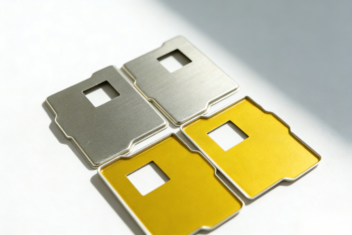
3. Myth: "Shielding cans are plug-and-play components."
Fact: First-time integration requires synchronized alignment between three interdependent deliverables:
- Custom mold development (for unique footprint or insulation patterns),
- Precision stamping with thickness tailored to frequency and rigidity requirements,
- Surface finish compatibility (e.g., tin plating for solderability vs. chemical nickel for long-term corrosion resistance).
→ Source: Product ID 718 specs + on integrated mold-to-stamping flow
4. Myth: "One shielding can design fits all module footprints."
Fact: Standard L4.4 and L6.5 shielding clips exist—but the shielding can itself must be footprint-matched to the PCB’s mounting pad geometry, thermal pad clearance, and adjacent component height. Off-the-shelf assumptions risk air gaps that degrade shielding attenuation at operational frequencies.
→ Source: Product ID 724 highlights “custom configurations to match mainstream module package footprints”
Where First-Time Adoption Typically Breaks Down
| Stage | Common Gap | Verified Boundary |
|---|---|---|
| Specification handoff | Engineering assumes ‘standard’ can = generic part number | No universal part numbers exist—every can is custom-stamped per drawing; no stock inventory “support by drawing, not catalog” |
| Mold development | Timeline assumed to be <2 weeks | Mold design & validation is iterative; lead time depends on complexity |
| Quality sign-off | Reliance on visual inspection only | Full quality control includes dimensional metrology, surface finish verification, and functional fit-check on reference PCB “standardized QC lab with full-process inspection” |
Next Steps for Compliance & Hardware Teams
- Before finalizing BOM: Confirm whether your shielding can requires one-piece, two-piece, or partial insulating coating configuration—each affects mold complexity, assembly sequence, and test repeatability. (Source: Product ID 722 summary)
- Before releasing drawings: Specify base material and surface finish together—tin plating on AL1060 behaves differently than on SPCC under reflow, impacting solder joint reliability.
- Before pilot run: Request first-article inspection report (FAIR) covering thickness, flatness, and positional tolerance—not just appearance.
If your current shielding can evaluation lacks traceable mold development records, material certifications, or stamped-part dimensional reports, the compliance risk isn’t theoretical—it’s already embedded in your supply chain.
Ready to Align Specification With Deliverable?
Dongguan Zhuoyi Precision provides documented mold development and precision stamping services for communication module, IoT module, smartphone/tablet, and POS terminal solution providers—with engineering support from drawing review through FAIR delivery.
Contact our technical team to request a shielding can feasibility assessment—including material recommendation, mold scope outline, and typical lead time guidance based on your PCB layout and performance targets.
Recommended
EMI Shielding Can
Precision EMI shielding cans designed for high-frequency circuits in communication modul...
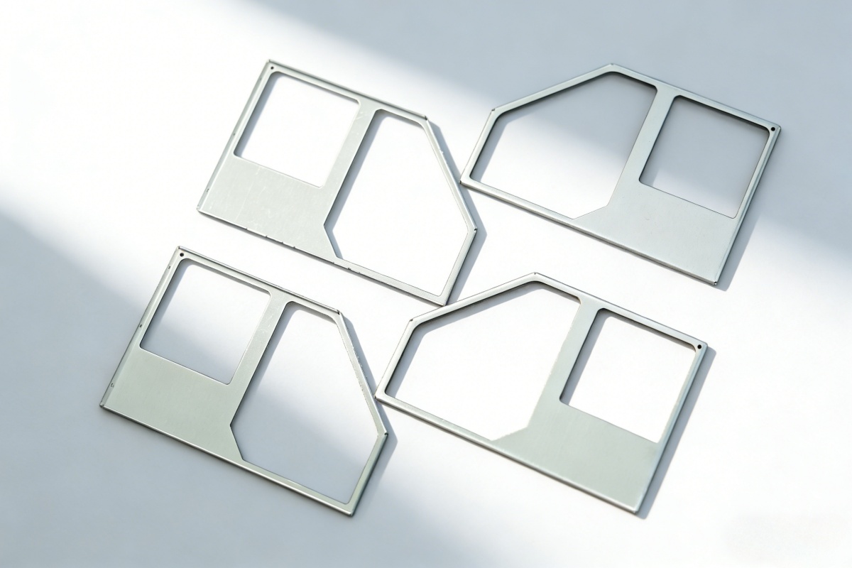
Shielding Can
An integrated metal enclosure structure designed for rapid installation and reliable EMI...
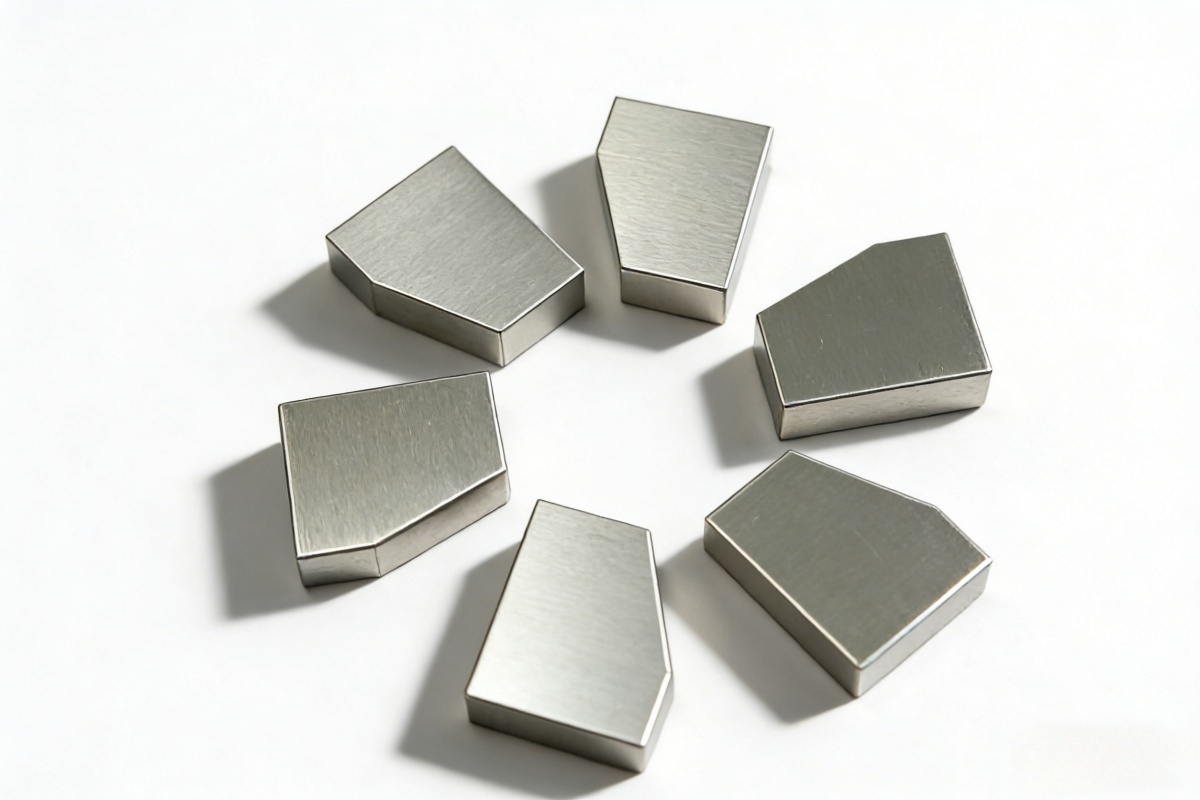
EMI Shielding Cans and Covers (EMI Shielding Structural Components)
Precision EMI shielding cans and covers engineered for high-frequency electronic devices...