

EMI Shielding Clips (L4.4 / L6.5 Series)
Precision L-shaped EMI shielding clips engineered for high-frequency circuits such as communication modules and IoT modules—designed for SMT assembly and repeatable rework, balancing EMI protection, space efficiency, and mass-production compatibility.
Highlights
- Available in standard sizes including L4.4 and L6.5, plus custom configurations to match mainstream module package footprints
- End-to-end in-house delivery—from tooling development to high-volume stamping—with first-sample lead time ≤15 working days
- Compliant with RoHS/REACH regulations; material certifications and factory inspection reports provided
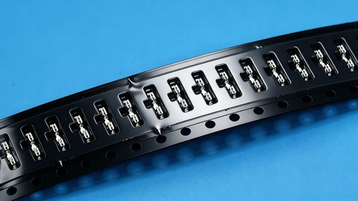
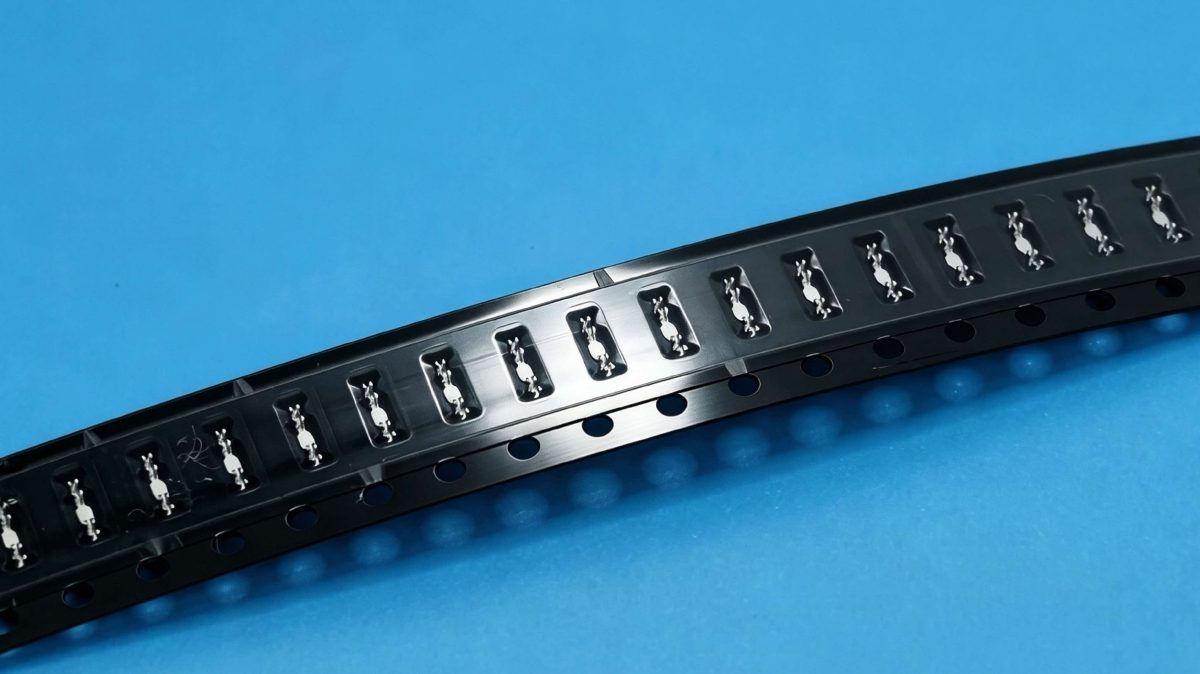
- SMT-line optimized: embossed carrier tape packaging, flatness ≤0.05 mm, coplanarity compliant
Specifications
- Structure
- L-shaped spring clip; single- or double-arm configuration available
- Common Materials
- SPCC (cold-rolled carbon steel), SECC (electro-galvanized steel)
- Surface Finish
- Tin plating, nickel plating, pre-tinned, black oxide (per requirement)
- Tolerance Class
- ±0.03 mm (critical dimensions), flatness ≤0.05 mm
- Packaging
- Embossed carrier tape (reel), anti-static bag + carton
In wireless communication devices (e.g., 4G/5G modules, Wi-Fi/BLE IoT modules, and smart terminal motherboards), electromagnetic interference (EMI) suppression is a critical step to ensure signal integrity and system stability. Traditional shielding frames require soldering for fixation, making maintenance difficult and occupying significant PCB area; in contrast, EMI shielding clips—structural innovation solutions—feature an elastic L-shaped body enabling rapid locking and reversible installation, significantly improving assembly efficiency and serviceability without compromising shielding performance.
Why do electronics solution companies choose custom EMI shielding clips?
Dongguan Zhuoyi Precision Hardware Co., Ltd. provides integrated services—including die development and stamping mass production—for mainstream EMI shielding clips such as the L4.4 and L6.5 series, targeting module-level customers.die development + stamping mass productionUnlike standard off-the-shelf components, custom EMI shielding clips precisely meet the following requirements:
- Structural Compatibility: Adjust clip arm length, opening/closing angle, and spring-back force according to customer-specific PCB cutout dimensions, pad layout, and shield cover thickness;
- Process Compatibility: Meet mass-production requirements including SMT reflow (peak temperature 260°C), embossed tape carrier packaging, and AOI inspectability;
Material & Surface Finish
: Standard substrates are SPCC/SECC; optional finishes include nickel plating, tin plating, or pre-tinning to ensure solderability and corrosion resistance;
Reliability Validation Support
: Support customers in completing insertion/removal cycle testing (≥50 cycles without plastic deformation), high-temperature/high-humidity storage (85°C/85% RH, 168 h), and vibration testing (10–2000 Hz).
Typical Application Scenarios
•Communication Modules: Used for localized RF front-end shielding, replacing full shielding frames to save routing space;
•IoT Modules: Compatible with miniaturized multilayer board structures, achieving reliable clamping within limited height (≤1.2 mm);
•POS Terminals / Industrial Control Motherboards: Maintain consistent clamping force under wide-temperature and vibration conditions, preventing EMI leakage due to loosening;
•Maintenance-Friendly Design: During maintenance, no hot-air rework station is required—simply remove the shield cover directly, eliminating risks of PCB pad damage and component thermal damage.
Selection Reference Table
Model:Applicable Shield Cover Thickness (mm); Clamping Stroke (mm); Recommended Installation Pitch (mm); Typical Material/Surface Finish
L4.4:0.2–0.3; 0.4–0.5; 8–12; SPCC + Tin Plating
L6.5:0.3–0.5; 0.5–0.7; 10–15; SECC + pre-tinned
Note: The above are general parameter benchmarks; actual specifications require structural feasibility analysis and tolerance optimization based on customer drawings or 3D models.